Treating a manufacturer’s headline drone payload capacity and maximum windless flight time as simultaneously achievable numbers causes search-and-rescue and medical-delivery sorties to fail when loaded multirotors hit premature low-voltage return-to-home triggers or lose pitch authority in mountain turbulence. In electric rotary-wing flight, every gram of added sensor gimbal, communications relay, or trauma cargo increases required hover power to the three-halves power of total takeoff mass (P_hover ∝ M_total^(3/2)), accelerating battery discharge current into non-linear Peukert capacity loss while shrinking the aircraft’s Thrust-to-Weight Ratio (TWR) margin against wind gusts and high density altitude.
UAS Triple Challenge (uastriplechallenge.com) is an independent technical publication named after the domain once used by the 2021–2022 First Responder UAS Triple Challenge prize competition and has no affiliation with NIST, Kansas State University, Mississippi State University, or any aircraft manufacturer.
An electric multirotor’s total takeoff mass M_total = M_empty + M_battery + M_payload remains constant from launch to touchdown unless cargo is dropped in flight. By Rankine-Froude actuator disk momentum theory (NASA NTRS 20200001899), electrical hover power scales as P_hover = ((M_total × g)^(3/2)) / (η_p × √(2 × ρ × A_disk)) + P_avionics. Increasing total takeoff mass by +25% raises induced hover power by (1.25)^(1.5) = +39.8%; combined with internal resistance voltage sag (I_bat × R_int) and Peukert electrochemical derating (t = C_nom / I^k, where k = 1.05–1.15), practical hover endurance drops as M_total^(-1.65 to -1.85), cutting operational flight time by 30% to 35%. Across public-safety platforms, operational mission endurance with a mandatory 20%–25% State of Charge (SoC) reserve equals 0.75x to 0.80x of the 0% SoC sea-level datasheet curve, while 14 CFR § 107.3 enforces a hard < 55.0 lb (24.95 kg) gross takeoff ceiling and mountain density altitude (DA) erases net payload capacity 2.5x to 3.3x faster than ambient air density declines.
| Engineering or Regulatory Parameter | Governing Equation / Statutory Rule | Baseline Sea-Level Reference (ISA 0 m, +15 °C) |
Loaded or High-Altitude Degradation Impact | Dominant Operational Failure Mode |
|---|---|---|---|---|
Actuator Disk Hover Power (P_hover) |
P_hover = ((M_total × g)^(3/2)) / (η_p × √(2 × ρ × A_disk)) + P_avionics |
1.00x baseline power (~586 W on 6.47 kg M350 RTK at 0 kg payload) |
+25% takeoff mass → +39.8% induced power; +42.2% mass (9.20 kg MTOW) → +69.6% induced power (~979 W) |
Planning search grid legs from unweighted hover watts and running out of battery mid-sector |
Peukert & Ohmic Endurance Scaling (t_hover) |
t_hover ∝ C_nom / I_bat^k where I_bat = P_hover / (V_ocv − I_bat × R_int) and k = 1.05–1.15 |
55 min lab (0% SoC) / 42–44 min operational (20% SoC reserve) at 0 kg load |
t_hover ∝ M_total^(-1.65): drops to 34–36 min at 0.93 kg, 28–31 min at 1.80 kg, and 23–25 min at 2.73 kg max load |
Assuming linear 1/M flight-time loss (-20% instead of actual -32% to -43%) |
Thrust-to-Weight Ratio (TWR) Floor |
TWR = T_max / (M_total × g); Hover Throttle ≈ (1 / TWR) × 100% |
TWR >= 2.0 : 1 to 2.5 : 1 (40%–50% hover throttle command; >= 100% thrust headroom) |
TWR = 1.5 : 1 to 1.65 : 1 (60%–67% hover throttle) leaves only 33% margin before 100% PWM saturation |
Differential roll/pitch/yaw saturation in > 25 kt gusts or canyon downdrafts; stator overheating (> 120 °C) |
Part 107 Gross Weight Cliff (14 CFR § 107.3) |
M_total = M_empty + M_battery + M_payload < 55.0 lb (< 24.95 kg) strict inequality |
Standard Part 107 RPIC; max useful payload ~8.6–8.7 kg (19.1 lb on 54.9 lb IF1200A) |
At >= 55.0 lb (e.g., 95 kg DJI FlyCart 30 carrying 30–40 kg), Part 107 is invalid; requires 49 U.S.C. § 44807 exemption + COA |
Launching an overloaded hexacopter at >= 55.0 lb under Part 107 without a § 44807 grant and COA |
Altitude Payload Derating (σ & DA) |
σ = ρ(h,T)/ρ_0 = (P/P_0)×(T_0/T_K); M_payload(h)/M_payload(0) = 1 − ((1 − σ)/f_payload_0) |
ρ_0 = 1.225 kg/m³ (σ = 1.00), 100% rated max thrust, 100% rated payload |
At 1,500 m (+25 °C, DA ~7,500 ft, σ = 0.81): -19% thrust, -35% to -45% payload; at 3,000 m (+15 °C, DA ~12,300 ft, σ = 0.70): -30% thrust, -50% to -73% payload |
Carrying sea-level max payload to mountain search scenes without derating or installing high-altitude propellers |
Cold-Soak Battery Impedance (R_int) |
V_term = V_ocv(SoC) − I_bat × R_int(T_cell) (Arrhenius Li+ diffusion) |
R_int ≈ 15–45 mΩ at +20 °C to +25 °C core cell temperature |
At -10 °C to -20 °C, R_int spikes 2.0x to 6.0x, triggering < 3.25 V/cell low-voltage cutoff with 50%+ chemical charge remaining |
Launching cold-soaked packs below +15 °C without active pre-heating and a 60 s low-hover soak check |
Actuator disk momentum theory: why hover power scales as M^(3/2)
In fixed-wing and turbine-helicopter aviation, gross aircraft weight decreases steadily over a sortie as liquid hydrocarbon fuel burns off. An electric multirotor experiences no fuel burn weight relief: its onboard lithium-polymer (LiPo) or semi-solid lithium-ion (Li-ion) battery pack retains 100% of its mass whether at 98% SoC on climbout or 20% SoC on final approach. Every flight-time calculation in our technical explainers and All Articles starts with the strict mass-budget identity:
M_total = M_empty + M_battery + M_payload
Where:
M_totalis the total gross takeoff mass (kg), producing downward gravitational weight forceW = M_total × g(N, with standard gravityg = 9.80665 m/s²).M_emptyis the dry airframe mass (kg), comprising the carbon-fiber center frame, foldable booms, landing gear, brushless DC (BLDC) outrunner motors, electronic speed controllers (ESCs), flight controller, GNSS/RTK receivers, and permanent wiring harnesses.M_batteryis the total mass of installed propulsion batteries (kg), such as2.70 kgfor two DJITB65packs (1.35 kgeach) or22.50 kgfor twoDB2000packs (11.25 kgeach).M_payloadis the useful mission load (kg), including quick-release gimbal dampers, electro-optical/thermal (EO/IR) camera payloads, LiDAR units, airborne data-relay transceivers, embedded AI vision processors such as the Teledyne FLIR Prism A-ISR, spotlights, loudspeakers, winches, or medical drop kits.
Step-by-step derivation of the actuator disk hover power equation
As formalized in NASA’s multirotor propulsion scaling analysis (NTRS 20200001899) and coupled aerodynamic-battery endurance models (Bauersfeld & Scaramuzza, arXiv:2003.03975), the electrical power required to sustain steady out-of-ground-effect (OGE, altitude z > 2 × D_rotor) hover follows four physical steps:
- Total Swept Rotor Disk Area (
A_disk): For an airframe withN_rnon-overlapping planar rotors of blade radiusR(m, or diameterD_rotor = 2 × R), the total swept actuator disk area is:A_disk = N_r × π × R² = N_r × (π / 4) × D_rotor²(m²) (Engineering note on coaxial multirotors: when two counter-rotating rotors are stacked vertically on the same boom—such as an8-rotor,4-armcoaxial octocopter—the lower rotor operates inside the contracted slipstream of the upper rotor. Aerodynamic interference introduces an induced-power penalty factorκ_coax ≈ 1.15 to 1.28, meaning a coaxial pair achieves an effective disk area equivalent to~78%–85%of two isolated planar rotors.) - Rankine-Froude Momentum Conservation and Induced Velocity (
v_i): To hold constant altitude in hover, total upward rotor thrustTmust equal total aircraft weight:T = M_total × g(N) Modeling the rotor system as an infinitely thin actuator disk that accelerates ambient air of densityρ(kg/m³) from rest far above the aircraft to induced downward velocityv_i(m/s) through the rotor plane and2 × v_iin the fully developed far wake, the mass flow rate through the swept disk ism_dot = ρ × A_disk × v_i(kg/s). By conservation of vertical momentum, total thrust equals mass flow rate times wake velocity change:T = m_dot × (2 × v_i) = 2 × ρ × A_disk × v_i²Solving for the hover induced velocityv_iyields:v_i = √(T / (2 × ρ × A_disk)) = √((M_total × g) / (2 × ρ × A_disk))(m/s) Notice that induced downwash velocity scales with the square root of disk loading (DL = T / A_disk, inN/m²). - Ideal Induced Mechanical Hover Power (
P_ideal): The minimum ideal mechanical power required to accelerate the air column downward at ratev_iis the product of thrust and induced velocity:P_ideal = T × v_i = (T^(3/2)) / √(2 × ρ × A_disk) = ((M_total × g)^(3/2)) / √(2 × ρ × A_disk)(W) - Total Electrical Hover Power at the Battery Bus (
P_hover): Real rotors incur non-uniform inflow, blade-tip vortex shedding, swirl losses, and airfoil profile drag captured by the rotor Figure of Merit (FM = P_ideal / P_shaft ≈ 0.65 to 0.78for rigid carbon-composite UAV blades). Simultaneously, the brushless DC motors incur copper winding (I²R) and iron core eddy-current losses (η_motor ≈ 0.82 to 0.90), while the MOSFET/GaN electronic speed controllers incur switching and conduction losses (η_esc ≈ 0.92 to 0.96). Combining these three stages defines the overall electromechanical-propulsive efficiency:η_p = FM × η_motor × η_esc ≈ 0.55 to 0.72(withη_p ≈ 0.62representative of commercial public-safety multirotors) Adding the continuous auxiliary hotel loadP_avionics(typically 25 to 90 Wfor flight control computers, RTK GNSS, O3/O4 video downlink, thermal gimbal motors, and payload processors) produces the complete electrical hover power equation:P_hover = ((M_total × g)^(3/2)) / (η_p × √(2 × ρ × A_disk)) + P_avionics(W)
Under International Standard Atmosphere (ISA) sea-level reference conditions (h = 0 m, standard temperature T_0 = +15.0 °C = 288.15 K, standard barometric pressure P_0 = 1013.25 hPa = 29.92 inHg, air density ρ_0 = 1.225 kg/m³, and g = 9.80665 m/s²), A_disk, ρ_0, and η_p are fixed for a given airframe. Consequently, aerodynamic hover power grows strictly as M_total^(3/2) (M_total^(1.5)).
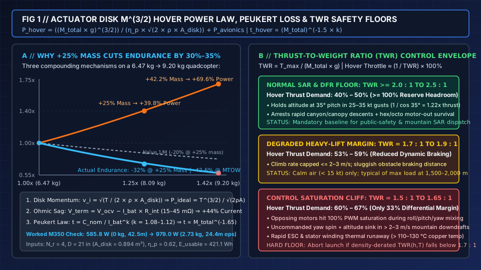
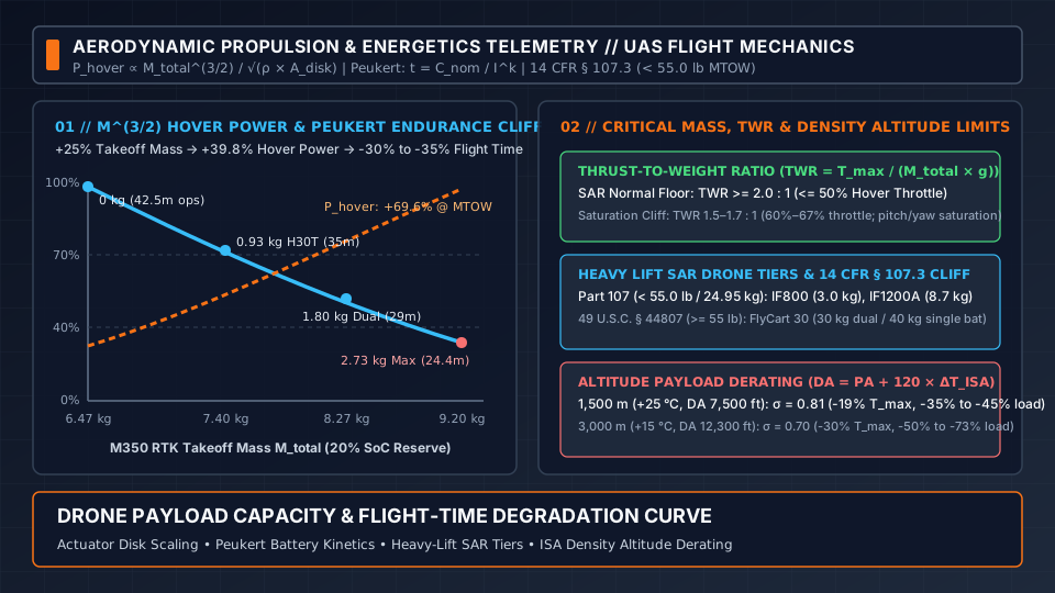
Figure 1: Coupled aerodynamic and electrochemical flight-time degradation showing why a +25% increase in total takeoff mass raises hover power by +39.8% and cuts practical endurance by 30%–35%, alongside Thrust-to-Weight Ratio (TWR) control authority boundaries.
Why +25% takeoff mass cuts operational endurance by 30% to 35% (and +42% mass cuts 40% to 45%)
Field operators frequently estimate payload flight-time penalties using a naïve linear inverse ratio (t_2 / t_1 = M_total_1 / M_total_2), assuming that adding +25% to takeoff weight (1.25x mass) reduces flight time by 20% (1 / 1.25 = 0.80). In physical reality, three compounding mechanisms stack on top of one another so that hover endurance degrades as M_total^(-1.65 to -1.85):
- Mechanism 1 — Super-Linear
M^(3/2)Aerodynamic Power Scaling (+39.8%Power for+25%Mass): Because induced power scales with takeoff mass to the1.5power:P_hover_2 / P_hover_1 = (M_total_2 / M_total_1)^(1.5)Mounting a1.62 kgdual-sensor payload onto a6.47 kgbaseline quadcopter increases total takeoff mass to8.09 kg(M_total_2 / M_total_1 = 1.250, or+25.0%). The aerodynamic power required to hover jumps by:(1.250)^(1.5) = 1.3975(+39.8%more hover power). When loaded to its structural maximum takeoff weight of9.20 kg(2.73 kgpayload, or+42.2%total mass increase), induced hover power jumps by:(9.20 / 6.47)^(1.5) = (1.4219)^(1.5) = 1.6957(+69.6%more hover power). - Mechanism 2 — Ohmic
I_bat × R_intTerminal Voltage Sag and Current Amplification: A battery pack’s loaded terminal voltageV_termis lower than its open-circuit voltageV_ocv(SoC)by the product of discharge currentI_batand pack DC internal resistanceR_int(typically 15 to 45 mΩacross a6Sto12Spack):V_term = V_ocv(SoC) − (I_bat × R_int)andI_bat = P_hover / V_termBecauseV_termsags deeper under heavy load, supplying+39.8%more electrical power at the ESC bus requires+43% to +46%more battery currentI_bat. Simultaneously, internal Joule heating wasted inside the cells (P_heat = I_bat² × R_int) more than doubles (1.44² = 2.07x). Furthermore, because the flight controller triggers critical low-voltage protection based on loaded terminal voltage (~3.20–3.30 V/cell), a deeperI_bat × R_intsag crosses the landing threshold earlier in the discharge curve. - Mechanism 3 — Peukert Electrochemical Capacity Derating (
t = C_nom / I^k): At higher discharge C-rates, lithium-ion diffusion gradients across the porous electrode structure reduce the extractable charge capacity before cell cutoff. Governed by Peukert’s law:t_discharge = H × (C_nom / (I_bat × H))^k(or in proportionality form,t_hover ∝ C_nom / I_bat^k) whereHis the rated discharge hour basis (typically 1 h),C_nomis nominal capacity (Ah), andkis the Peukert exponent (k = 1.05 to 1.15for high-discharge UAV LiPo and semi-solid Li-ion cells, withk ≈ 1.08–1.10typical at+20 °C). SubstitutingI_bat ∝ (M_total)^(1.5 × 1.03)into Peukert’s equation yields:t_hover ∝ (M_total)^(-1.5 × 1.03 × k) ≈ (M_total)^(-1.65 to -1.78)At+25%takeoff mass (1.25x),(1.25)^(-1.68) = 0.687, representing a31.3%loss of hover time (30%–35%in field operations once climb and gust reserves are included). At+42.2%takeoff mass (1.422x),(1.422)^(-1.68) = 0.553, representing a44.7%loss of hover time (40%–45%across mixed forward-cruise and hover search profiles).
Worked numerical verification: DJI Matrice 350 RTK propulsion and endurance check
To verify that the actuator disk and Peukert equations reproduce published OEM telemetry without empirical fudge factors, consider a 4-rotor quadcopter matching the physical dimensions of the DJI Matrice 350 RTK:
- Airframe & Rotor Geometry:
N_r = 4planar rotors, standard2110spropeller diameterD_rotor = 21 in = 0.5334 m(blade radiusR = 0.2667 m). Single rotor swept area isπ × (0.2667 m)² = 0.2235 m²; total actuator disk area isA_disk = 4 × 0.2235 m² = 0.8938 m². - Propulsive & Battery Constants: Sea-level ISA air density
ρ_0 = 1.225 kg/m³, overall electromechanical-propulsive efficiencyη_p = 0.62, baseline avionics drawP_avionics = 35 W(45 Wwith dual gimbals active), and Peukert exponentk = 1.08. TwoTB65intelligent flight batteries store2 × 263.2 Wh = 526.4 Whtotal nameplate energy (5,880 mAhat44.76 Vnominal per pack). Enforcing a mandatory20% SoCpublic-safety landing reserve yieldsE_usable = 526.4 Wh × 0.80 = 421.1 Whof usable mission energy at baseline C-rate. - Case A — Bare Airframe (
0.00 kgPayload,M_total = 6.47 kg): With3.77 kgempty airframe plus2.70 kgfor twoTB65batteries, total hover thrust isT = 6.47 kg × 9.80665 m/s² = 63.45 N(disk loadingDL = 71.0 N/m²). Induced velocity isv_i = √(63.45 / (2 × 1.225 × 0.8938)) = √(63.45 / 2.1898) = 5.383 m/s. Ideal mechanical power isP_ideal = 63.45 N × 5.383 m/s = 341.5 W. Dividing byη_p = 0.62and adding35 Wavionics hotel load gives total electrical hover power:P_hover(0 kg) = (341.5 W / 0.62) + 35 W = 550.8 W + 35 W = 585.8 W(pack currentI_bat ≈ 13.1 A, or~1.11Cacross two parallel5.88 Ahpacks). Operational hover endurance with20% SoCreserve is(421.1 Wh / 585.8 W) × 60 = 43.1 min(~42.5 minaccounting for takeoff climb, or53.9 minto0% SoC—matching DJI’s55 minwindless datasheet specification flown at8 m/swhere translational lift trims induced power by~3%). - Case B — Structural Maximum Payload (
2.73 kgPayload,M_total = 9.20 kgMTOW): Adding2.73 kgof payload increases takeoff mass by+42.2%to9.20 kg(T = 90.22 N, disk loadingDL = 100.9 N/m²). Induced velocity rises tov_i = √(90.22 / 2.1898) = 6.419 m/s. Ideal mechanical power rises by+69.6%toP_ideal = 90.22 N × 6.419 m/s = 579.1 W. Total electrical hover power with45 Wavionics/payload draw is:P_hover(2.73 kg) = (579.1 W / 0.62) + 45 W = 934.0 W + 45 W = 979.0 W(+67.1%total electrical power; pack current rises toI_bat ≈ 22.4 Aunder load sag). Applying the Peukert discharge factor(979.0 / 585.8)^(1.08) = (1.6712)^(1.08) = 1.741xeffective depletion rate reduces operational hover time (20% SoCreserve) to:t_hover(2.73 kg) = 43.1 min / 1.741 = 24.8 min(~24–25 minpure hover, or30–31 minto0% SoC), reproducing DJI’s published M350 RTK payload-endurance curve within half a minute.
Takeaway: Never prorate multirotor endurance linearly with weight; calculate power demand using (M_total_2 / M_total_1)^(1.5) and apply a 1.65 to 1.75 negative mass exponent to operational flight time.
Thrust-to-weight ratio (TWR): the 2.0:1 SAR safety floor vs control saturation
While actuator disk power and Peukert kinetics govern how long a loaded aircraft stays airborne, the Thrust-to-Weight Ratio (TWR) governs whether the flight controller retains sufficient differential motor headroom to keep the airframe stable in wind gusts, canyon downdrafts, and aggressive braking maneuvers. For an airframe with N_r motors each capable of generating maximum static thrust T_max_motor(h, T) at the local air density, total aircraft TWR is:
TWR = T_max / (M_total × g) = (N_r × T_max_motor(h, T)) / (M_total × g)
Because steady level hover requires total thrust T = M_total × g, the fraction of maximum available thrust consumed simply to hold altitude is the inverse of TWR:
Thrust_hover_fraction (%) = (1 / TWR) × 100%
(Note: on ESCs with linear thrust-mapped throttle curves, hover throttle percentage equals (1 / TWR) × 100%; on legacy RPM-linear ESCs where T ∝ RPM², hover PWM command approximates √(1 / TWR) × 100%.)
| Thrust-to-Weight Regime | TWR Ratio Range |
Hover Thrust Demand (1 / TWR) |
Reserve Thrust Headroom | Bank-Angle Wind Authority & Motor-Out Survival | Public-Safety Dispatch Verdict |
|---|---|---|---|---|---|
| 1. Standard Public-Safety & SAR Design Target | TWR >= 2.0 : 1 to 2.5 : 1 |
40% – 50% of max thrust |
>= 100% to 150% excess thrust above hover weight |
Sustains 30°–35° pitch/roll tilt into 25–35 kt (12–18 m/s) gusts without altitude sink; arrests 4–5 m/s descents; enables hexacopter (N_r = 6) or coaxial octocopter (N_r = 8) single-motor-out recovery |
Mandatory operational floor for wilderness SAR, DFR rooftop launch, and forest canopy missions |
| 2. Degraded Heavy-Lift or Mid-Altitude Margin | TWR = 1.7 : 1 to 1.9 : 1 |
53% – 59% of max thrust |
70% to 90% excess thrust above hover weight |
Climb rate restricted to <= 2.0–3.0 m/s; longer horizontal stopping distance at grid turnarounds; hexacopter single-motor loss at full weight results in forced descent rather than level hold |
Caution regime: acceptable only in light winds (< 15 kt) with gentle turn rates and obstacle clearance |
| 3. Control Authority Saturation Cliff | TWR = 1.5 : 1 to 1.65 : 1 |
60% – 67% of max thrust |
<= 50% total (<= 33% per-axis differential margin) |
Attitude control saturation: opposing motors hit 100% PWM cap during roll/pitch/yaw mixing in turbulence, causing uncommanded yaw spin, altitude loss in turns, and stator thermal runaway (> 110–130 °C) |
Hard no-go limit: never launch a SAR or cargo mission if density-derated TWR(h, T) falls below 1.7 : 1 (1.5 : 1 absolute emergency floor) |
Why multirotors lose attitude stability below TWR = 1.7 : 1
Unlike a conventional single-main-rotor helicopter that changes blade pitch cyclically via a mechanical swashplate while keeping rotor RPM constant, a fixed-pitch multirotor controls pitch, roll, and yaw exclusively through differential motor thrust (ΔT):
- Pitch and Roll Moments: To pitch nose-down into a headwind or arrest forward groundspeed at the end of a parallel sweep or expanding-square search track, the flight controller must command
+ΔTon the rear rotors and-ΔTon the front rotors. - Yaw Reaction Torque: Because aerodynamic drag torque on a spinning propeller scales as
Q = C_Q × ρ × n² × D_rotor⁵, yawing the nose into the wind—or preventing uncommanded yaw in crosswind shear—requires raising the speed of clockwise (CW) motors while lowering counter-clockwise (CCW) motors. - Tilted Thrust Vector Cosine Penalty (
1 / cos θ): When a multirotor banks or pitches by angleθto hold position against a horizontal wind drag forceF_wind = 0.5 × ρ × C_d × A_front × V_wind², only the vertical component of rotor thrustT_vert = T_total × cos(θ)supports aircraft weightM_total × g. Holding level altitude at a35°pitch angle in a30 kt(15.4 m/s) wind requires total thrust to increase by1 / cos(35°) = 1.221x(+22.1%) before any gust recovery or attitude control deltaΔTis applied. - Canyon Downdraft Arrest and Hex/Octo Motor-Out Redundancy: If an overloaded aircraft is hovering at
TWR = 1.55 : 1(64.5%average thrust command) and encounters a3 m/slee-side mountain downdraft while banking25°, baseline thrust demand jumps past80%. The instant the PID attitude controller commands+25%differential thrust on the downwind-rear motor to level the airframe and hold heading, that motor clips at100%pulse-width modulation (PWM) saturation. Once one motor saturates, the flight controller must either sacrifice yaw stability (allowing the nose to spin uncontrollably) or shed vertical thrust across all motors (causing the aircraft to sink into terrain or forest canopy). Simultaneously, running BLDC motors continuously above65%–75%throttle drives high RMS phase currents through the copper stator windings, pushing winding temperatures past110 °C–130 °Cwhere neodymium (NdFeB) rotor magnets risk irreversible partial demagnetization.
Takeaway: Size every payload and battery combination so that local density-derated TWR stays at or above 2.0 : 1 (<= 50% hover throttle), and treat TWR = 1.7 : 1 as an operational abort threshold.
Real-world payload vs flight-time degradation curves across three SAR tiers
Published manufacturer specification sheets report Maximum Flight Time measured in windless sea-level air (ISA 0 m, +15 °C) at a constant optimal forward cruise speed (where translational lift reduces induced inflow velocity v_i by 15%–22% compared to stationary hover) flown all the way down to 0% SoC.
In real public-safety, Drone as First Responder (DFR), and wilderness search-and-rescue operations, running a battery below 15%–20% SoC under heavy payload current invites sudden cell voltage collapse (< 3.20 V/cell) and permanent cathode/anode degradation, inflating recurring battery replacement lines in agency DFR cost quote worksheets. Standard public-safety operating procedures therefore enforce a 20% to 25% reserve SoC on touchdown (25%–30% at automated return-to-home initiation). Consequently:
t_operational_SAR ≈ (0.75 to 0.80) × t_datasheet_0pct_SoC
As established in our explainer on drone search optimization under forest canopy and our radiometric guide to thermal drone search and rescue, total search effort Z = V × T × W (where V is groundspeed, T is productive time on scene, and W is sensor sweep width) depends directly on how much net endurance remains after subtracting transit time t_transit from t_operational_SAR:
T_on_scene = (0.78 × t_datasheet(M_payload)) − (2 × d_transit / V_transit)
Mounting a heavier dual-gimbal sensor package increases sweep width W only if the resulting drop in T_on_scene does not shrink total swept area Z below the single-sensor baseline.
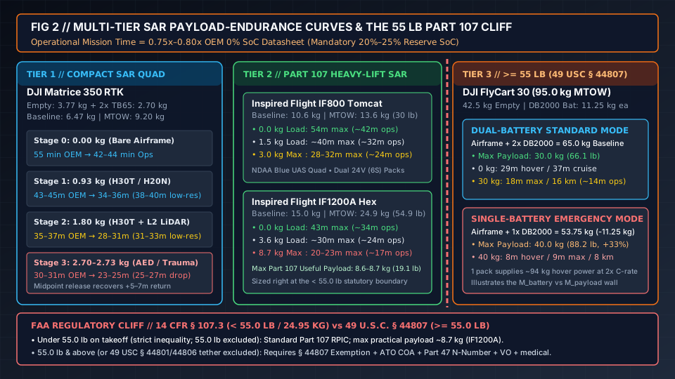
Figure 2: Payload-to-endurance degradation curves across Tier 1 compact ISR quadcopters (DJI Matrice 350 RTK), Tier 2 Part 107 medium/heavy-lift SAR platforms (Inspired Flight IF800 Tomcat and IF1200A), and Tier 3 Section 44807 heavy cargo multirotors (DJI FlyCart 30).
Tier 1: Compact tactical ISR and dual-sensor SAR quadcopters (DJI Matrice 350 RTK)
The DJI Matrice 350 RTK represents the standard public-safety and SAR tactical quadcopter class (M_empty = 3.77 kg without batteries; 2.70 kg for 2 × TB65 batteries; baseline takeoff mass M_total = 6.47 kg; structural maximum takeoff weight MTOW = 9.20 kg; maximum total payload capacity M_payload_max = 2.73 kg). Operators must distinguish between the total airframe payload ceiling (2.73 kg) and the single gimbal damper structural limit (960 g): any load exceeding 960 g must be distributed across the dual downward gimbal mount, the upward gimbal mount, or a rigid belly frame adapter.
| Configuration Stage | Installed Payload Hardware | Payload Mass (M_payload) |
Total Takeoff Mass (M_total) |
Relative Aerodynamic Hover Power (M/M_0)^1.5 |
OEM Datasheet Max Flight Time (0% SoC) |
SAR Operational Endurance (20% SoC Reserve) |
Primary Search & Rescue Mission Role |
|---|---|---|---|---|---|---|---|
| Stage 0 — Bare Baseline | None (single downward gimbal connector only) | 0.00 kg (0 g) |
6.47 kg (14.26 lb) |
1.00x (~586 W total bus draw) |
55 min |
42 – 44 min |
Ferry, compass/IMU calibration, or pilot proficiency flight |
| Stage 1 — Single Multi-Sensor SAR Gimbal | Zenmuse H20N (878 g) or Zenmuse H30T (920 g radiometric thermal + zoom + LRF) |
0.93 kg (930 g; under 960 g single damper cap) |
7.40 kg (16.31 lb, +14.4% mass) |
1.22x (+22.3% induced power + ~20 W sensor draw) |
43 – 45 min |
34 – 36 min (38–40 min at 12% low-reserve ceiling) |
Primary day/night thermal canopy search, missing-person localization, and overwatch |
| Stage 2 — Dual-Gimbal SAR + LiDAR or Tactical Peripherals | Zenmuse H30T (920 g) + Zenmuse L2 LiDAR (905 g), or H30T + GL60 Plus spotlight + loudspeaker |
1.80 kg (1,800 g on dual downward gimbal) |
8.27 kg (18.23 lb, +27.8% mass) |
1.45x (+44.5% induced power + ~45 W dual sensor draw) |
35 – 37 min |
28 – 31 min (31–33 min at 12% low-reserve ceiling) |
Simultaneous thermal victim search + 3D forest canopy penetration LiDAR mapping or night voice hailing |
Stage 3 — Structural Max Payload (MTOW Ceiling) |
Compact EO/IR camera + belly drop hook carrying ultralight AED (1.6 kg), hemorrhage trauma kit, or marine throw ring |
2.70 – 2.73 kg (100% of rated payload) |
9.20 kg (20.28 lb, +42.2% mass) |
1.70x (+69.6% induced power + Peukert 1.74x draw) |
30 – 31 min |
23 – 25 min (25–27 min with midpoint payload drop) |
Emergency point-to-point trauma kit, pediatric AED, radio repeater, or flotation device delivery |
Tactical Midpoint Payload-Drop Endurance Recovery: In Stage 3 emergency medical or swiftwater rescue missions, if a 2.00 kg trauma pack or inflatable life ring is released at the target coordinates (midpoint drop), the aircraft does not fly the return leg at 9.20 kg. The instant the 2.00 kg load separates, total mass reverts from 9.20 kg (~979 W hover power) to 7.20 kg (~680 W hover power)—cutting outbound power consumption by 30.5% on the return leg and recovering 5 to 7 minutes of reserve flight time compared to carrying a fixed 2.70 kg non-jettisonable sensor package for the entire sortie. Conversely, when a delivery drone lowers cargo via an onboard electromechanical winch—as analyzed in our Munson Healthcare Phase Two medical drone delivery report—the dead weight of the winch reel, motor, and housing (typically 0.8 to 1.4 kg) remains attached to the airframe on the return trip, and winch motor jams under load directly threaten flight completion.
Tier 2: Medium and heavy-lift SAR and cargo multirotors (IF800, IF1200A, and FlyCart 30)
When public-safety agencies step up from a ~9 kg quadcopter to carry heavy dual-return LiDAR scanners, multi-band cellular/MANET base stations, or multi-kilogram resupply loads, airframe scaling splits into two distinct classes: NDAA-compliant Part 107 medium/heavy-lift platforms engineered to stay strictly below 55.0 lb (24.95 kg), and heavy cargo coaxial octocopters operating above 55.0 lb under 49 U.S.C. § 44807.
| Aircraft Platform & Rotor Architecture | Empty + Battery Baseline Mass (M_empty + M_battery) |
Maximum Takeoff Weight (MTOW) |
Maximum Rated Payload (M_payload_max) |
Payload Fraction (M_payload / MTOW) |
Published Endurance Degradation Curve (0% SoC Max → 20% SoC Operational) |
|---|---|---|---|---|---|
Inspired Flight IF800 Tomcat (NDAA Blue UAS Quadcopter) |
10.6 kg (23.4 lb with 2 × 24V / 6S smart batteries) |
13.6 kg (30.0 lb — Part 107 compliant) |
3.0 kg (6.6 lb) |
22.1% |
• 0.0 kg: 54 min max (~42 min ops)• 1.5 kg (3.3 lb EO/IR or LiDAR): ~40 min max (~32 min ops)• 3.0 kg (6.6 lb max load): 28 – 32 min max (~23–25 min ops) |
Inspired Flight IF1200A (NDAA Blue UAS Heavy-Lift Hexacopter) |
15.0 kg (33.0 lb with 2 × 12S 22–25 Ah LiPo packs) |
23.6 – 24.9 kg (52.0 – 54.9 lb — sized at the Part 107 ceiling) |
8.6 – 8.7 kg (19.1 lb under Part 107) |
34.9% |
• 0.0 kg: 43 min max (~34 min ops)• 3.6 kg (8.0 lb heavy LiDAR/comms relay): ~30 min max (~24 min ops)• 8.7 kg (19.1 lb max Part 107 load): 20 – 23 min max (~16–18 min ops) |
DJI FlyCart 30 — Dual-Battery Mode (Coaxial 8-Rotor Heavy Cargo) |
65.0 kg (42.5 kg empty + 2 × DB2000 batteries at 11.25 kg each) |
95.0 kg (209.4 lb — requires 49 U.S.C. § 44807 exemption) |
30.0 kg (66.1 lb standard dual-pack rating) |
31.6% |
• 0.0 kg (65.0 kg takeoff): 29 min hover / 37 min (28 km) forward cruise• 30.0 kg (95.0 kg MTOW): 18 min max flight / 16 km range at 15 m/s (~13–14 min ops) |
DJI FlyCart 30 — Single-Battery Emergency Mode (Mass-Swap Configuration) |
53.75 kg (42.5 kg empty + 1 × DB2000 battery at 11.25 kg) |
93.75 – 95.0 kg (206.7 – 209.4 lb) |
40.0 kg (88.2 lb — gained by shedding one 11.25 kg battery) |
42.7% |
• 0.0 kg (53.75 kg takeoff): 15 min hover• 40.0 kg (93.75 kg takeoff): 8 min hover / 9 min max flight / 8 km range (~6.5 min ops) |
The battery-vs-payload mass-swap wall: why DJI FlyCart 30 trades 50% endurance for +10 kg payload
The contrast between the DJI FlyCart 30 Dual-Battery Standard Mode (30 kg payload) and Single-Battery Emergency Mode (40 kg payload) illustrates the fundamental mass-budget ceiling of electric VTOL aircraft. Because the airframe’s structural and aerodynamic maximum takeoff weight is fixed at MTOW = 95.0 kg (209.4 lb) and empty airframe weight is M_empty = 42.5 kg, only 95.0 kg − 42.5 kg = 52.5 kg of combined mass budget is available for M_battery + M_payload:
- In Dual-Battery Mode, two
DB2000batteries (38,000 mAh,52.36 V,1,989.6 Wh,11.25 kgeach) consume22.50 kgof that budget (M_empty + M_battery = 65.0 kg), leaving exactly30.0 kgfor cargo (18 minmaximum loaded flight time over16 km). - In Single-Battery Emergency Mode, removing one
11.25 kgDB2000battery drops baseline weight to53.75 kg, allowing the operator to load40.0 kgof emergency cargo (M_total = 93.75 kg, a+33.3%increase in payload capacity). However, because that single1,989.6 Whbattery pack must now supply the entire~94 kghover power on its own, its per-pack discharge currentI_batdoubles (2.0x C-rate). Under Peukert’s law (t ∝ C_nom / I^k) and doubledI_bat × R_intvoltage sag, loaded flight time plunges by more than50%—from18 minutesdown to8 minuteshover (9 minutesforward flight /8 kmrange).
At the opposite end of the delivery spectrum, high-cadence suburban retail drone delivery networks—such as Wing and Walmart’s planned 2027 Denver and Seattle expansion—restrict package payloads to 1.1–2.3 kg (2.5–5.0 lb) and transition from vertical lift to fixed-wing cruise (L/D ≈ 8–12) specifically to escape the multirotor M^(3/2) hover power curve.
Tier 3: The FAA 14 CFR § 107.3 (< 55.0 lb) regulatory cliff vs 49 U.S.C. § 44807
In the United States, the transition from a Tier 2 hexacopter like the Inspired Flight IF1200A (54.9 lb MTOW) to a Tier 3 heavy lifter like the DJI FlyCart 30 (209.4 lb MTOW) crosses a rigid statutory boundary:
- Strict Inequality Under
14 CFR § 107.3(< 55.0 lb): Federal Aviation Regulations part 107 defines a small unmanned aircraft as “an unmanned aircraft weighing less than 55 pounds on takeoff, including everything that is on board or otherwise attached to the aircraft.” An aircraft weighing exactly55.0 lb(24.948 kg) or more on the launch scale is excluded from Part 107. This is the exact statutory threshold enforced in the historical 2021–2022 NIST PSCR competition documented in our UAS Triple Challenge Archive, where competition FAQ rules prohibited any aircraft weighing55 lbor more, capped total multi-aircraft system weight below120 lb, and required teams to deploy, search, and return within60 minutes. - Actively Tethered Public-Safety Exception (
49 U.S.C. § 44801 & § 44806): As detailed in our tethered drone power and fiber-optic relay explainer, when a public-safety agency operates an actively tethered UAS under49 U.S.C. § 44806(capped at<= 150 ft AGLunless otherwise authorized), the55.0 lbstatutory weight ceiling includes the aircraft and onboard payload but excludes the weight of the taut tether cable (1.60 to 2.60 kgfor a100 mElistair power-and-fiber line). Free-flying multirotors enjoy no such exclusion: every gram of battery, gimbal, drop rigging, and cargo counts on the takeoff scale. - Heavy Unmanned Aircraft Exemption (
49 U.S.C. § 44807): Because14 CFR § 107.205does not list the< 55.0 lbdefinition in§ 107.3as a waivable regulation, an operator cannot apply for a Part 107 waiver to fly a55+ lbdrone, nor can an emergency Special Governmental Interest (SGI) addendum convert a Part 107 certificate into heavy-lift authority unless backed by an underlying heavy-UAS authorization. Civil operation at>= 55.0 lbrequires a formal Petition for Exemption under49 U.S.C. § 44807published via the Federal Register docket (or a14 CFR Part 21Special Airworthiness Certificate) paired with an FAA Air Traffic Organization Certificate of Waiver or Authorization (COA).
| Compliance Dimension | Under 55.0 lb (< 24.95 kg) — 14 CFR Part 107 |
55.0 lb and Above (>= 24.95 kg) — 49 U.S.C. § 44807 Heavy UAS |
|---|---|---|
Maximum Gross Takeoff Mass (M_empty + M_battery + M_payload) |
Strictly < 55.0 lb (< 24.948 kg) on takeoff including all batteries, mounts, sensors, and cargo (14 CFR § 107.3) |
>= 55.0 lb (>= 24.948 kg), covering 55 to 250+ lb heavy cargo, mountain resupply, and wildfire suppression multirotors |
Maximum Practical Useful Payload (f_payload ≈ 30%–35%) |
~7.0 to 9.0 kg (15.4 to 19.8 lb) ceiling (e.g., IF1200A carries 8.6–8.7 kg / 19.1 lb inside a 54.9 lb MTOW with 15.0 kg of airframe + batteries) |
15.0 to 40.0+ kg (33.0 to 88.2+ lb) (e.g., DJI FlyCart 30 carries 30.0 kg dual-battery or 40.0 kg single-battery at 95.0 kg MTOW) |
| FAA Airworthiness & Operating Authorization | Standard 14 CFR Part 107 rules (or Public Aircraft COA for qualifying government entities); no airworthiness certificate required | Formal 49 U.S.C. § 44807 Grant of Exemption (or 14 CFR Part 21 Special Airworthiness Certificate) + mandatory ATO COA |
| Aircraft Registration & Marking | Online FAADroneZone Part 48 registration ($5, instant registration number) |
Formal 14 CFR Part 47 Aircraft Registry (N-Number) with notarized bill of sale, affidavit of ownership, and physical N-number marking |
| Pilot Certificate, Medical & Crew Mandate | Single Part 107 Remote Pilot in Command (RPIC); no FAA medical certificate; Visual Observer (VO) optional unless required by BVLOS waiver |
Typically mandates Part 107 RPIC + Part 61 pilot certificate or Third-Class / Driver’s License medical, mandatory Visual Observer (VO), OEM platform training, and >= 500 ft non-participant standoff |
Takeaway: Under 14 CFR Part 107, useful multirotor payload hits a hard physical wall at ~8.7 kg (19.1 lb) because airframe structure and batteries occupy ~15–16 kg of the < 24.95 kg (55.0 lb) takeoff limit; lifting 10–40 kg requires transitioning to a 49 U.S.C. § 44807 exemption and COA.
Density altitude and high-altitude payload derating in mountain SAR
Wilderness search-and-rescue teams frequently deploy into high-elevation mountain terrain (1,500 to 3,500+ m / 4,920 to 11,500+ ft MSL in the Rocky Mountains, Sierra Nevada, Cascades, or Alps), often during warm summer afternoons when solar heating raises canyon air temperatures 15 °C to 22 °C above standard atmospheric values. As established in the FAA Pilot’s Handbook of Aeronautical Knowledge (FAA-H-8083-25C), Chapter 11: Aircraft Performance, high elevation and high outside air temperature (OAT) combine to raise Density Altitude (DA)—inflicting a severe double aerodynamic penalty on multirotor aircraft and forcing strict altitude payload derating.
International Standard Atmosphere (ISA) air density and density altitude equations
- ISA Temperature Lapse Rate (
ISA_Temp_C): In the International Standard Atmosphere (ISA), sea-level standard temperature isT_0 = +15.0 °C(288.15 K/59.0 °F) and standard pressure isP_0 = 1013.25 hPa(29.92 inHg), yielding sea-level air densityρ_0 = 1.225 kg/m³. Across the troposphere (h <= 11,000 m), standard temperature decreases linearly at6.5 °C per 1,000 m(1.98 °C per 1,000 ft):ISA_Temp_C(h_m) = 15.0 − (0.0065 × h_m)ISA_Temp_C(PA_ft) = 15.0 − (1.98 × (PA_ft / 1,000)) - Standard Barometric Pressure Ratio (
P(h) / P_0): At geometric elevationh_m(m), standard barometric pressure follows the hydrostatic exponent:P(h_m) = P_0 × (1 − (0.0065 × h_m) / 288.15)^(5.25588)In operational field checks using a local altimeter settingAltimeter_inHg, Pressure AltitudePA (ft)is:PA (ft) = Elevation_ft + 1,000 × (29.92 − Altimeter_inHg) - Aviation Density Altitude Formula (
DA): Density Altitude (DA, infeet) is the pressure altitude corrected for non-standard outside air temperatureOAT_C(°C):DA (ft) ≈ PA (ft) + 120 × (OAT_C − ISA_Temp_C)Every+10 °C(+18 °F) above standardISA_Temp_Cadds+1,200 ft(+366 m) to the effective Density Altitude the rotors feel. - Ideal Gas Air Density Ratio (
σ): By the ideal gas law for dry air (ρ = P / (R_specific × T_K)whereT_K = OAT_C + 273.15), the dimensionless air density ratioσ(sigma) relative to sea level (ρ_0 = 1.225 kg/m³) is:σ = ρ(h, T) / ρ_0 = (P(h) / P_0) × (288.15 / (OAT_C + 273.15))
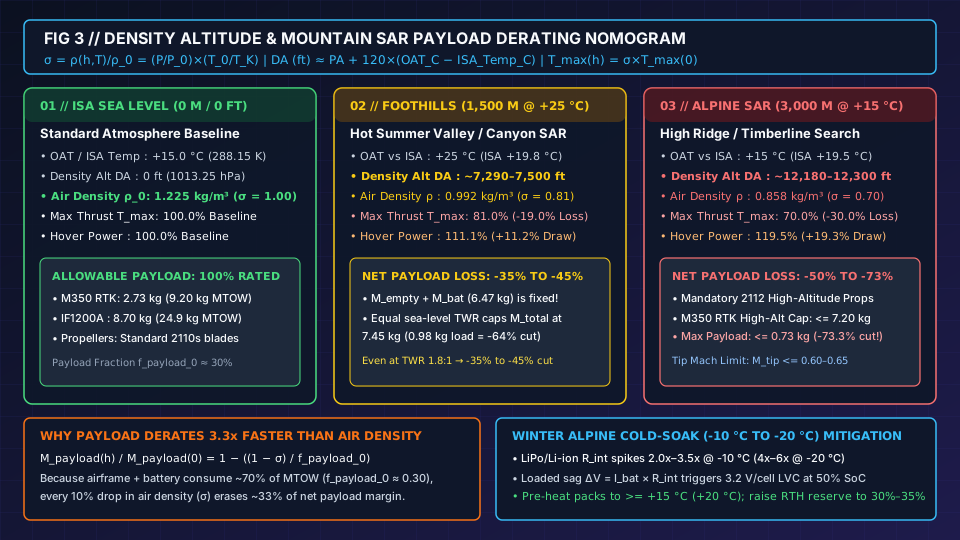
Figure 3: Mountain SAR altitude payload derating nomogram comparing sea-level ISA baseline (0 m, +15 °C), hot foothills canyon conditions (1,500 m, +25 °C, DA ~7,500 ft), and high-alpine timberline search conditions (3,000 m, +15 °C, DA ~12,300 ft), alongside cold-weather battery impedance rules.
The double aerodynamic penalty: linear thrust loss (σ) + inverse-square-root power rise (σ^(-1/2))
Aerodynamic rotor thrust is governed by the blade-element thrust coefficient equation:
T = C_T × ρ × n² × D_rotor⁴
where C_T is the dimensionless propeller thrust coefficient (determined by blade pitch angle and chord profile), ρ is ambient air density (kg/m³), n is rotational speed (rev/s), and D_rotor is propeller diameter (m). When an aircraft climbs to high density altitude (σ = ρ / ρ_0 < 1.0), two simultaneous physical limits tighten around the propulsion system:
- Penalty 1 — Maximum Available Thrust Drops Linearly with Air Density (
T_max(h) = σ × T_max(0)): Why can a multirotor not simply spin its motors faster at high altitude to recover full sea-level maximum thrustT_max(0)? Maximum rotor rotational speedn_maxis hard-capped by two physical ceilings:- DC Bus Voltage Ceiling (
KV × V_bat): A brushless motor’s unloaded top speed cannot exceed its velocity constantKV(RPM/V) multiplied by loaded battery voltageV_term(n_max_loaded <= 0.85 × KV × V_term). - Compressibility and Blade-Tip Mach Limit (
M_tip <= 0.60–0.65): Because the speed of sounda_sound = √(γ × R_gas × T_K)decreases at colder high altitudes, spinning a21-inchto30-inchpropeller faster drives the advancing blade-tip Mach numberM_tip = (π × D_rotor × n) / a_soundpast0.60–0.65, triggering transonic drag divergence, shock-induced boundary-layer separation, and severe vibration. Withn_max,D_rotor, andC_Tfixed, maximum achievable rotor thrust drops in direct 1:1 proportion to the air density ratioσ:T_max(h, T) = σ × T_max(0)
- DC Bus Voltage Ceiling (
- Penalty 2 — Hover Power at Any Fixed Mass Increases as
σ^(-1/2): To generate the same hover thrustT = M_total × gin thinner air (ρ = σ × ρ_0), the flight controller must command a higher hover RPMn(h) = n(0) × σ^(-1/2), accelerating a smaller mass of air downward at a higher induced velocityv_i(h) = v_i(0) × σ^(-1/2). Substitutingρ = σ × ρ_0into our actuator disk equation shows that electrical hover power for a fixed takeoff mass increases inversely with the square root of air density:P_hover(h, T) = P_hover(0) × σ^(-1/2)
Why net payload capacity derates 2.5x to 3.3x faster than air density
Here lies the trap that catches mountain SAR teams off guard: when maximum thrust T_max drops by 19% (σ = 0.81) or 30% (σ = 0.70), net allowable payload capacity M_payload_max(h) does not drop by 19% or 30%—it drops by 35% to 73%.
To maintain the same safe Thrust-to-Weight Ratio TWR (e.g., TWR = 2.0 : 1) at altitude h as at sea level, maximum allowable gross takeoff mass M_total_max(h) must scale down linearly with σ:
M_total_max(h) = σ × M_total_max(0)
However, the operator cannot shave weight off the carbon airframe (M_empty) or the flight batteries (M_battery). Subtracting the fixed dead weight M_empty + M_battery from both sides gives the Fractional Altitude Payload Derating Law:
M_payload_max(h) = (σ × M_total_max(0)) − (M_empty + M_battery)
Dividing by the sea-level rated payload M_payload_max(0) = M_total_max(0) − (M_empty + M_battery) and defining the sea-level payload mass fraction f_payload_0 = M_payload_max(0) / M_total_max(0) yields:
M_payload_max(h) / M_payload_max(0) = 1 − ((1 − σ) / f_payload_0)
Because f_payload_0 on commercial multirotors is typically 0.25 to 0.35 (25% to 35% of MTOW is payload, while 65% to 75% is fixed airframe plus battery):
- Every
10%loss in air density (1 − σ = 0.10) wipes out0.10 / 0.30 = 33.3%of net payload capacity if the operator preserves sea-levelTWR! - Even when operators accept a slightly degraded
TWRat altitude (e.g., allowing TWR to step down from 2.2 : 1 at sea level to 1.8 : 1 at altitude) or swap to higher-pitch High-Altitude Low-Noise Propellers (such as DJI2112blades on the Matrice 350 RTK, which increase blade pitchC_Tby~10%–12%to prevent RPM saturation above3,000 m), net payload capacity still shrinks2.0x to 2.5xfaster than air density.
| Elevation & Temperature Regime | Standard ISA_Temp_C |
Density Altitude (DA) |
Air Density ρ & Ratio σ |
Fixed-RPM Max Thrust (T_max(h)) |
Constant-Mass Hover Power (σ^(-1/2)) |
Net Payload Derating (Equal Sea-Level TWR vs Practical High-Alt Prop Limit) |
Worked M350 RTK (9.20 kg Sea-Level MTOW, 6.47 kg Baseline, 2.73 kg Max Payload) |
|---|---|---|---|---|---|---|---|
1. ISA Sea Level Baseline (0 m / 0 ft, +15.0 °C OAT) |
+15.0 °C |
0 ft (0 m) |
1.225 kg/m³ (σ = 1.000) |
100.0% |
100.0% (1.000x) |
0% derating (100% of rated payload) |
Full 9.20 kg MTOW; 2.73 kg max payload (H30T + L2 or full trauma drop kit) |
2. Hot Foothills / Summer Canyon (1,500 m / 4,921 ft, +25.0 °C OAT) |
+5.25 °C (ISA +19.75 °C) |
~7,290 – 7,500 ft (~2,250 m) |
0.992 kg/m³ (σ = 0.810, -19.0%) |
81.0% (-19.0% max thrust) |
111.1% (+11.1% hover power; -13% flight time) |
-64.1% at equal TWR; -35% to -45% with TWR 1.8:1 allowance |
Equal-TWR max mass = 0.81 × 9.20 = 7.45 kg (0.98 kg payload); practical 1.8:1 TWR limit = 1.50 – 1.75 kg payload (single H30T + light spotlight) |
3. High-Alpine Timberline SAR (3,000 m / 9,843 ft, +15.0 °C Summer OAT) |
-4.50 °C (ISA +19.50 °C) |
~12,180 – 12,300 ft (~3,730 m) |
0.858 kg/m³ (σ = 0.700, -30.0%) |
70.0% (-30.0% max thrust on std props) |
119.5% (+19.5% hover power; -21% flight time) |
-50% to -73.3% net payload loss + Mandatory High-Altitude Propellers |
Standard 2110s props saturate (0.70 × 9.20 = 6.44 kg < 6.47 kg bare weight!). With mandatory 2112 High-Altitude Props, DJI caps MTOW at <= 7.20 kg → max payload <= 0.73 kg (-73.3% cut) |
4. Extreme High-Altitude Ridge / Pass (4,500 m / 14,764 ft, +5.0 °C OAT) |
-14.25 °C (ISA +19.25 °C) |
~17,070 ft (~5,200 m) |
0.736 kg/m³ (σ = 0.601, -39.9%) |
60.1% (-39.9% max thrust) |
129.0% (+29.0% hover power; -28% flight time) |
-80% to -90% net payload loss (single ultralight sensor only) |
Requires 2112 High-Altitude Props and strict single-sensor configuration (<= 0.30–0.50 kg); dual-gimbal launch is prohibited |
Look closely at the 3,000 m (+15 °C, DA ~12,300 ft) High-Alpine SAR row in the table above:
- At
3,000 mgeometric elevation on a+15 °Csummer afternoon, barometric pressure isP(3000) = 1013.25 × (1 − 19.5 / 288.15)^(5.25588) = 701.1 hPa(P / P_0 = 0.6919) and temperature ratio is288.15 / 288.15 = 1.000, givingσ ≈ 0.692 to 0.700(ρ = 0.858 kg/m³). - On standard sea-level
2110spropellers,0.70 × 9.20 kg = 6.44 kg—meaning the aircraft loses30%of its maximum thrust and requires nearly70%throttle just to hover its own6.47 kgempty+battery weight if sea-levelTWRwere demanded! - That is why DJI’s official Matrice 350 RTK specifications mandate replacing standard
2110sblades with higher-pitch2112High-Altitude Low-Noise Propellers for operations above3,000 m(extending maximum ceiling from5,000 mto7,000 m) while imposing a hard high-altitude takeoff weight limit ofM_total <= 7.20 kg. Subtracting the6.47 kgbaseline airframe + battery weight leaves a maximum allowable alpine payload of7.20 kg − 6.47 kg = 0.73 kg(730 g)—a73.3%payload reduction compared to its2.73 kgsea-level rating! At730 g, a920 gZenmuse H30T is already190 gover the high-altitude cap unless the crew flies a lighter payload or operates below the7.20 kghigh-altitude curve.
Winter mountain SAR: cold-soak (-10 °C to -20 °C) battery internal resistance spikes
During winter mountain search-and-rescue missions (-10 °C to -20 °C ambient temperature at 2,000 to 3,500 m), cold air increases ρ relative to summer (σ improves by +8% to +12%, partially restoring aerodynamic rotor thrust). However, sub-freezing temperatures introduce an even more abrupt failure mode inside the lithium battery pack:
- Arrhenius Electrolyte Viscosity and SEI Impedance Spike (
2.0x to 6.0x R_int): Between+25 °Cand-15 °C, the ionic conductivity of organic carbonate liquid electrolytes drops sharply andLi+charge-transfer kinetics across the anode Solid Electrolyte Interphase (SEI) slow exponentially. Pack DC internal resistanceR_intincreases by2.0x to 3.5xat-10 °Cand4.0x to 6.0xat-20 °C. - Instantaneous Loaded Voltage Sag (
ΔV = I_bat × R_int) and Premature LVC: Suppose a12S(44.76 Vnominal) battery pack hasR_int = 30 mΩat+25 °C, producing a modest0.90 Vsag (0.075 V/cell) under a30 Aheavy-hover climb current. If that same pack is launched cold-soaked at-15 °CwhereR_inthas spiked4xto120 mΩ, a30 Athrottle punch produces an immediate3.60 Vterminal voltage drop (0.30 V/cell). Even with55%–65% SoCchemical energy still stored in the electrodes (V_ocv ≈ 3.72 V/cell), loaded terminal voltage plunges to3.42 V/cellin steady hover and dips below the flight controller’s3.20–3.30 V/cellcritical low-voltage cutoff (LVC) during the first wind gust or climb—forcing an immediate automated autoland into snow or trees. - Mandatory Three-Step Cold-Weather SAR Protocol:
- Pre-Warm Batteries to
>= +15 °C to +20 °CBefore Arming: Store flight batteries inside an insulated, thermostatically heated case (+20 °C to +30 °C) until strapping them onto the aircraft, or activate onboard self-heating (e.g., DJI TB65 / TB30 internal heating films, which draw ~40–60 W to warm cells from -20 °C to >= +15 °C) prior to motor start. - Execute a
60-SecondLow-Hover Thermal Soak: Immediately after liftoff in< 0 °Cair, hold a stationary hover2 to 3 mabove the launch pad for60 seconds. Verify on telemetry that internalI² × R_intself-heating keeps core cell temperature rising above+20 °Cand confirm that maximum inter-cell voltage deviation stays tight (ΔV_cell < 0.08 to 0.10 V) before climbing over canopy or terrain. - Raise Return-to-Home Reserve to
30%–35% SoC: Because convective wind chill in forward flight cools the battery casing and the steepest discharge voltage cliff occurs below30% SoCat low temperatures, increase the mandatory landing reserve from20%(temperate air) to30%–35% SoCin sub-zero operations.
- Pre-Warm Batteries to
Takeaway: At mountain search elevations, compute Density Altitude DA and air density ratio σ before selecting payloads, install high-altitude propellers when DA exceeds 9,000–10,000 ft (3,000 m), and never launch a lithium battery whose core temperature reads below +15 °C.
Pre-flight payload, endurance, and density-altitude verification checklist
Before dispatching a public-safety or search-and-rescue multirotor with a new sensor combination, communications relay, or medical drop package, complete this six-step engineering verification sequence:
| Verification Step | Calculation / Measurement Formula | Pass Threshold / Go Criteria | Abort / Corrective Action if Failed |
|---|---|---|---|
1. Calibrated Gross Takeoff Scale Check (M_total) |
M_total = M_empty + M_battery + M_payload (weighed on a calibrated digital platform scale with all cables, dampers, SD cards, and drop hooks attached) |
M_total <= MTOW_structural AND M_total < 55.0 lb (24.948 kg) for Part 107 flights (or within § 44807 exemption limit) |
Shed secondary accessories, switch to a lighter single gimbal, or transition to a 49 U.S.C. § 44807 heavy-lift airframe and COA |
| 2. Mount & Damper Structural Distribution Check | Compare each gimbal / mounting point mass M_mount_i against the OEM single-connector rating (e.g., <= 960 g per downward gimbal damper on M350 RTK) |
M_mount_i <= M_damper_max AND center of gravity (CG) within <= 10–15 mm of rotor geometric center |
Redistribute sensors onto a dual-gimbal bracket, install heavy-duty stiffer elastomer dampers, or rebalance battery tray position |
3. Local Density Altitude (DA) & Density Ratio (σ) |
ISA_Temp_C = 15 − 0.0065 × h_m; DA (ft) = PA_ft + 120 × (OAT_C − ISA_Temp_C); σ = (P(h)/P_0) × (288.15 / (OAT_C + 273.15)) |
Record exact DA (ft) and σ (e.g., σ = 0.81 at 1,500 m / +25 °C; σ = 0.70 at 3,000 m / +15 °C) |
If DA > 9,500 ft (~3,000 m), install OEM high-altitude propellers (e.g., DJI 2112) and apply the high-altitude MTOW cap (<= 7.20 kg on M350 RTK) |
4. Derated Thrust-to-Weight Ratio (TWR(h, T)) |
T_max(h, T) = σ × T_max(0) (or +10% with high-alt props); TWR(h, T) = T_max(h, T) / (M_total × g) |
TWR(h, T) >= 2.0 : 1 (<= 50% hover throttle) for normal SAR/wind; >= 1.8 : 1 in calm valley air |
Hard Abort if TWR(h, T) < 1.7 : 1 (> 59% hover throttle): apply the Fractional Payload Derating Law M_payload(h)/M_payload(0) = 1 − ((1 − σ)/f_payload_0) |
5. Coupled M^(3/2) + Peukert + Altitude On-Scene Time (T_on_scene) |
P_hover(M, h) = P_hover(0) × (M_total / M_0)^(1.5) × σ^(-0.5); t_ops = 0.78 × t_0_datasheet × (M_total / M_0)^(-1.68) × σ^(0.54) |
Productive search time T_on_scene = t_ops − (2 × d_transit / V_transit) >= 15–20 min per battery set (with 20%–25% reserve SoC, or 30%–35% in < 0 °C cold) |
Shorten search sector transit distance (move launch point closer to datum), widen track spacing S, or stage hot-swappable battery sets |
| 6. Battery Core Thermal & Cell-Balance Gate | Read BMS telemetry for T_cell_min (°C), pack cycle count, and loaded hover cell delta ΔV_cell = V_cell_max − V_cell_min during 60 s hover at 2–3 m AGL |
T_cell >= +15.0 °C (+20 °C preferred) prior to launch AND ΔV_cell < 0.08 V under hover load |
Engage active transport-case or onboard self-heating until T_cell >= +15 °C; retire any battery pack showing ΔV_cell >= 0.10 V under hover load |
Complete worked mountain SAR mission dispatch example
Suppose a county mountain rescue team is dispatched on a warm July afternoon to search a heavily timbered drainage at 1,500 m (4,921 ft) geometric elevation where outside air temperature is OAT_C = +25.0 °C (77.0 °F) and local barometric pressure matches standard altitude pressure (P(1500) = 845.6 hPa, PA = 4,921 ft). The crew operates a DJI Matrice 350 RTK (M_empty + M_battery = 6.47 kg, sea-level MTOW = 9.20 kg, sea-level max thrust T_max(0) ≈ 180.4 N, giving TWR(0) = 2.00 : 1 at 9.20 kg). They want to know whether to launch with Option A (Single Zenmuse H30T thermal/zoom gimbal, 0.93 kg) or Option B (Dual gimbal: H30T + Zenmuse L2 LiDAR + spotlight, 2.10 kg) to search a grid 1.8 km (1,800 m) up-canyon at V_transit = 10 m/s:
- Step 1 & 3 — Density Altitude (
DA) and Air Density Ratio (σ):- Standard temperature at
1,500 misISA_Temp_C = 15.0 − (0.0065 × 1,500) = +5.25 °C. - The afternoon temperature anomaly is
OAT_C − ISA_Temp_C = 25.0 − 5.25 = +19.75 °C. - Effective Density Altitude is
DA = 4,921 ft + (120 × 19.75) = 4,921 + 2,370 = 7,291 ft(~2,222 m). - Air density ratio is
σ = (845.6 / 1013.25) × (288.15 / (25.0 + 273.15)) = 0.8345 × 0.9665 = 0.8065(ρ = 0.988 kg/m³, a-19.3%loss of air density).
- Standard temperature at
- Step 4 — Derated Thrust-to-Weight Ratio (
TWR) Comparison:- At
σ = 0.8065, maximum available static thrust on standard2110spropellers drops from180.4 NtoT_max(1500m, +25°C) = 0.8065 × 180.4 N = 145.5 N. - Option B (
2.10 kgpayload,M_total = 8.57 kg, weightW = 84.04 N):TWR_B = 145.5 N / 84.04 N = 1.73 : 1(hover thrust demand =57.8%). In a mountain canyon with afternoon thermal gusts (20–25 kt),TWR = 1.73 : 1sits right on the edge of the degraded caution regime. - Option A (
0.93 kgH30T payload,M_total = 7.40 kg, weightW = 72.57 N):TWR_A = 145.5 N / 72.57 N = 2.005 : 1(hover thrust demand =49.9%). Option A preserves the full2.0 : 1public-safetyTWRfloor at7,291 ftDensity Altitude!
- At
- Step 5 — Productive Time on Scene (
T_on_scene) with20% SoCReserve:- Two-way canyon transit (
2 × 1,800 m = 3,600 mat10 m/splus climb/descent) consumest_transit = 6.5 min. - Option B (
M_total = 8.57 kgatσ = 0.8065): Sea-level operational endurance (20%reserve) at8.57 kgis43.1 min × (8.57 / 6.47)^(-1.68) = 43.1 × 0.623 = 26.8 min. Applying the high-altitude hover power penalty (σ^(-0.5) = 1.114xpower →1.114^1.08 = 1.123xdepletion rate) reduces mountain operational endurance to26.8 / 1.123 = 23.9 min. Subtracting6.5 mintransit leaves onlyT_on_scene = 17.4 minper flight. - Option A (
M_total = 7.40 kgatσ = 0.8065): Sea-level operational endurance at7.40 kgis43.1 min × (7.40 / 6.47)^(-1.68) = 43.1 × 0.798 = 34.4 min. Dividing by the1.123xdensity-altitude depletion factor gives30.6 mintotal mountain flight time. Subtracting6.5 mintransit yieldsT_on_scene = 24.1 minof productive canyon search time per battery set—delivering+38.5%more productive search coverageZper sortie while keeping full2.0 : 1gust authority.
- Two-way canyon transit (
Takeaway: Running the six-step mass, TWR, and density-altitude check before takeoff prevents launching an over-encumbered dual-payload configuration when a single multi-sensor gimbal delivers both a >= 2.0 : 1 thrust margin and +38% more productive search time on scene.
Analytical alignment across physics, datasheets, and statutes
To keep flight-mechanics calculations verifiable across procurement, mission planning, and regulatory compliance, this explainer separates three distinct record types:
- Aerodynamic and Electrochemical Equations: The actuator disk momentum equation
P_hover = ((M_total × g)^(3/2)) / (η_p × √(2 × ρ × A_disk)) + P_avionics, disk loading scaling, and blade-tip Mach limits follow NASA’s multirotor conceptual design scaling report (NTRS 20200001899). The coupled non-linear Peukert battery discharge law (t = C_nom / I^k) and internal resistance voltage drop model (V_term = V_ocv − I_bat × R_int) follow Bauersfeld and Scaramuzza (IEEE RA-L / arXiv:2003.03975). Standard atmosphere pressure, temperature lapse rate, and density altitude (DA = PA + 120 × (OAT_C − ISA_Temp_C)) follow Chapter 11 of the FAA Pilot’s Handbook of Aeronautical Knowledge (FAA-H-8083-25C). - Manufacturer Specification Baselines: Empty weights, battery capacities, maximum takeoff weights, single-gimbal damper limits, and sea-level
0% SoCflight-time points are taken directly from published specification sheets for the DJI Matrice 350 RTK (3.77 kgempty,6.47 kgwith2 × TB65,9.20 kgMTOW,55 minmax windless), DJI FlyCart 30 (42.5 kgempty,65.0 kgdual-battery baseline,95.0 kgMTOW,30 kgdual-battery /18 minvs40 kgsingle-battery /8–9 min), Inspired Flight IF800 Tomcat (3.0 kgmax payload,54 minto28–32 min), and Inspired Flight IF1200A (8.6–8.7 kgmax Part 107 payload inside a52.0–54.9 lbMTOW,43 minto20–23 min). - Statutory and Historical Competition Boundaries: The
< 55.0 lb(24.95 kg) small unmanned aircraft gross takeoff threshold is cited from14 CFR § 107.3, heavy-UAS exemption procedures from49 U.S.C. § 44807, actively tethered public-safety cable weight exclusions from49 U.S.C. § 44801and§ 44806, and historical first-responder contest constraints (< 55 lbper aircraft,< 120 lbtotal system weight,<= 60 minmission cycle) from the October 25, 2021 archived FAQ of the First Responder UAS Triple Challenge.